Extended Reach: the Fact File
Time to push network cabling beyond the limits
Enterprises are increasingly adopting hybrid and multi-cloud environments to achieve the right balance of performance, cost, and flexibility. These environments allow businesses to leverage the advantages of both on-premises and cloud infrastructure.

As shown in Figure 1, the global industrial IoT (IIoT) chipset market is expected to experience a healthy 26.2% compounded annual growth rate (CAGR) between now and 2030. As a result, the global market for IIoT is estimated to increase from $147.2 billion in 2023 to $391.8 billion by 2028, a CAGR of 21.6%.
Moreover, the widespread use of edge-based, network-connected devices is no longer confined to the manufacturing and industrial sectors. Commercial and retail enterprises are now investing in network devices and management platforms.
The growth in edge-based connectivity presents a number of key challenges for enterprise network managers. Among them: how to extend the reach of their networks to deliver the required power and bandwidth beyond the traditional 100-meter distance limitation. Existing structured cabling architectures and standards can only go so far, and new extended-reach applications are continually emerging.
In this Enterprise Source fact file, we’ll dive deeper into the challenge of extended-reach power and data delivery. We’ll explore the various options and best practices for supporting connected devices at any distance from the telecom room (TR). Toward the end, we’ll show you how far a bit of out-of-the-box thinking can take you.
Before discussing how to solve the problem, let’s understand it a little better. Why exactly is there a 100 m limit?
The 100 m distance limitation—as codified in the industry standards (namely, ANSI/TIA-568, ISO 11801 and other cabling standards for commercial buildings)—is based on the electrical limitations of twisted-pair copper cabling. As the signal travels from one end of the cable to the other, its strength is affected by certain parameters, primarily insertion loss. The longer the cable, the greater the insertion loss. Based on these performance parameters, the industry standardized on the 100 m distance.
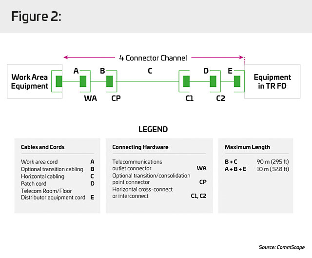
The distance limitation represents a worst case scenario for a given application and length when conducting a signal at the cable’s maximum frequency. It assumes a four-connector channel using a 90 m trunk and a 5 m patch cable at either end.
The limit was standardized in the 1990s and has stood the test of time even as higher-frequency applications and new cable constructions have entered the market. In that time, network equipment vendors cost-optimized their transceivers based on the 100 m limit—further solidifying it as the accepted distance boundary.
Why have just one standard for distance?
It is interesting to note that the 100 m limit applies to all cable categories—from Category 2, introduced in 1991, to Category 7A, which debuted in 2010 as a steppingstone to 40 Gbps. The capabilities of the various generations of category cabling have steadily increased, but the distance limitation has remained constant. Why not develop standards for each generation of category Ethernet? The simple answer is that using a higher category cable on the same applications extends the supportable distance by only a few meters at best. But there’s more to it than that.
Having a different standard for each cable category provides marginal benefits; not doing so, however, creates multiple opportunities. Standardizing on 100 m for all cable types provides a uniform target for manufacturers—and facility architects involved in floor planning—and eliminates the need and cost to test and certify each cable type to a different standard. Moreover, it enables customers to mix and match cabling from different manufacturers and ensures interoperability with active network equipment.
The effect of application and environment
While cable type has minimal effect on supportable distances, the application has a greater effect. A good example is power over Ethernet (PoE). A PoE+ (PoE type 2) application can support up to 30 watts of power over 150 m or more. The maximum distance depends on the speed required. Not counting special designs such as those requiring SYSTIMAX® GigaREACH™ (see below), the maximum horizontal distance at 10 Mbps is 185 m; at 100 Mbps it drops to 150 m. The environmental conditions such as operating temperature will also have an impact on the maximum supportable distance.
This being said, the 100 m channel limit has a significant effect on how enterprise networks are designed and deployed. Network managers must support more devices located farther from power sources and have high confidence that it will work. So, what are their options?
Would you like to read offline?
Download a PDF version of this article to read again later.
Stay informed!
Subscribe to The Enterprise Source and get updates when new articles are posted.
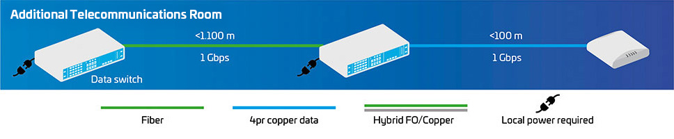
To reach connected devices located more than 100 m from the existing telecom room (TR), one solution is to simply add one or more TRs closer to the devices. From a perspective of space, cost and maintenance, this approach is the most expensive—and it’s difficult to justify for only one or two devices. An alternative is to deploy a wall-mounted cabinet with a switch and panel. While that is less costly, space can be scarce, and there’s still the issue of running power to the cabinet.
Pros
- Consistent architecture/media across the site
- Supports power over Ethernet (PoE)
- Supports up to 10G
Cons
- Not always possible
- Requires more space (and costs)
- Intermediate TR requires power
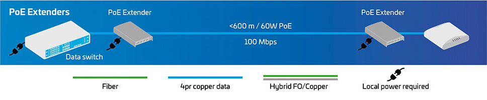
Another approach is to install an in-line PoE extender between the power source equipment and device. This divides the channel into two links—one on each side of the extender. Each link can span 100 m, enabling network designers to double the length of the channel while adhering to the standards.
However, a PoE extender (a.k.a. “repeater”) is subject to the power and bandwidth limitations of the PoE technology and cable medium used. This means it still needs local power and is limited as to the number of devices it can support. A PoE extender also requires dedicated space and, without careful tracking and location documentation, management and troubleshooting can be difficult.
Pros
- Good solution for a few devices
- Inexpensive and standards based
- Uses existing copper plant
Cons
- Finding space can be difficult
- Hard to manage if all extenders aren’t carefully documented
- Power may be hard to access in some areas
- Difficult to troubleshoot
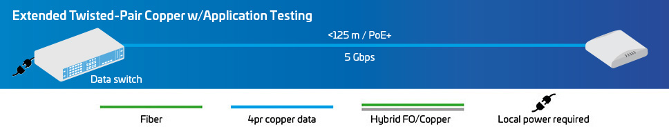
A third option for delivering power and data beyond the 100 m limit is to simply use a longer twisted-pair cabling link. While this method is not supported by the cabling standards, it is possible to use the application standards in conjunction with application testing to create a reliable link. Application standards help network designers gauge whether a specific application can run on a link segment, regardless of the cabling components used and the distance traversed.
For a more detailed analysis of this approach and the use of application standards and application testing, check out this article from Cabling Installation & Management.
Thoroughly vetted and correctly installed, the extended twisted-pair solution supports centralized management and efficient PoE delivery while reducing the number of link components and providing familiar RJ45 connectivity and installation.
Pros
- Easiest, least complex design
- Direct PoE from a PoE-enabled switch
- Familiar RJ45 connectivity and installation
- Familiar architecture
- Excellent data/power support for edge devices
- Easy to troubleshoot
- No additional points of failure
- Inexpensive
Cons
- Not supported by cabling standards
- Extra testing—in-lab and/or on-site
- Each new application must be re-vetted
- Not all high-bandwidth applications supported over extended distance
- Makes the design application-specific
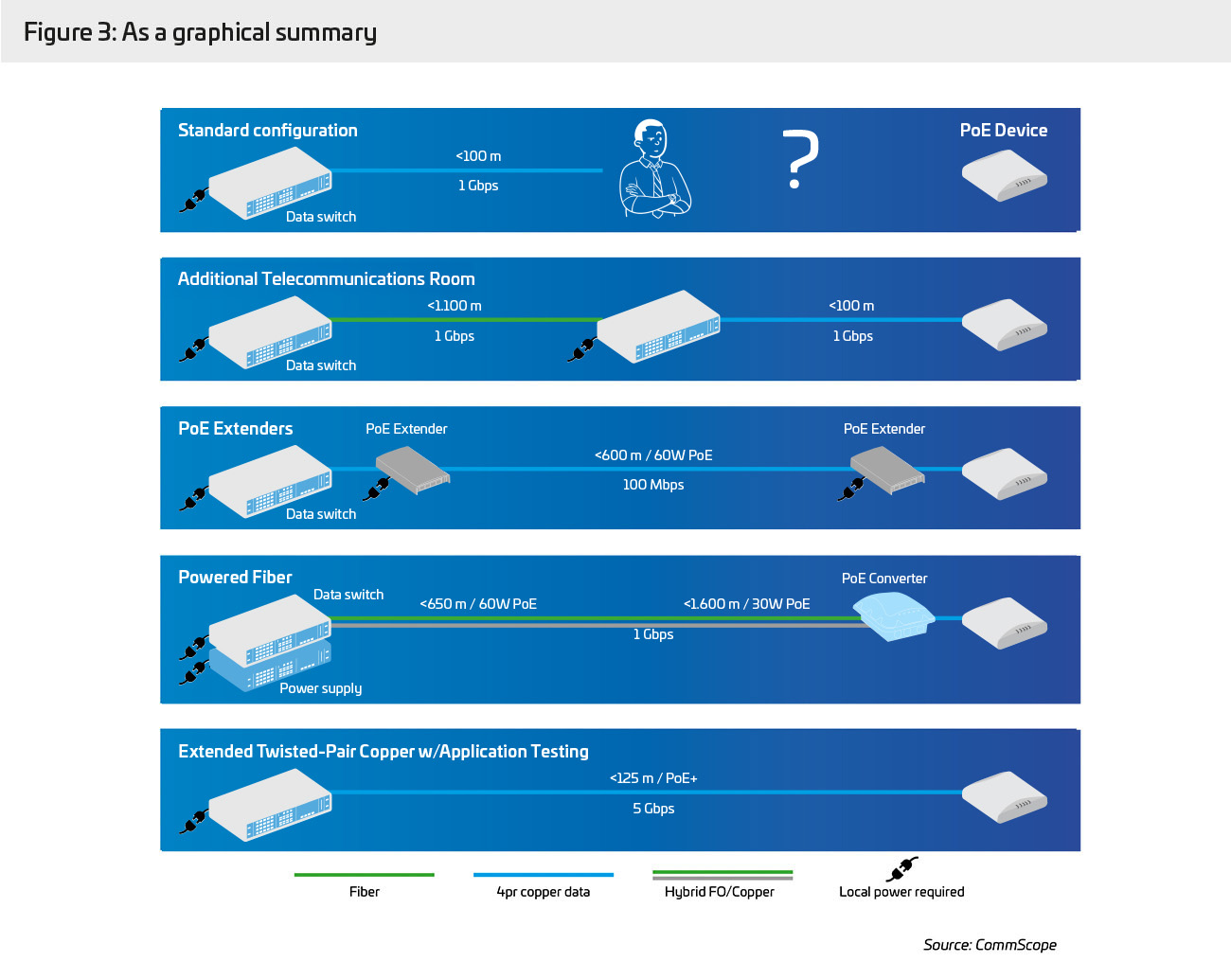
To briefly summarize the three approaches:
Option 1, adding TRs: The cost, space and intermediate power required to add more TRs are problematic. Even if you could justify committing these resources, it’s difficult to justify the disruptions to your normal workflow.
Option 2, using PoE extenders: Here, the issue isn’t the time and cost of the installation, but the effective management of the network—specifically troubleshooting issues. As service-level agreements for network uptime become more demanding, this option becomes less appealing.
Option 3, extend the copper infrastructure: This solution is the easiest and most cost-efficient to implement. Plus, it provides a familiar platform, RJ45 connectivity and centralized management. The drawbacks are performance verification and lack of a standards-supported roadmap.
Each approach has its pros and cons, and each offers specific uses cases that allow you to extend your Ethernet reach beyond 100 m. The question is: Can any of them be “refined” to the point where the pros outweigh the cons in a majority of scenarios?
At CommScope, we’ve been working for years to solve the extended reach challenge. As you might imagine, there is no single solution that addresses the wide range of use cases. Therefore, we’ve developed not one or two extended reach solutions, but four—each offering an innovative approach that attacks the issue from a different perspective.
Utility grade infrastructure

Working with industry leaders and Underwriters Laboratories (UL), CommScope developed a standards-compliant convergent infrastructure capable of connecting any device in a building—regardless of where it is located or its power and data needs: Utility Grade Infrastructure (UTG).
UTG is a complete technology platform, assurance program, and design approach. It unlocks a smart building’s full potential by redefining the infrastructure layer to support building subsystems, technologies and applications.
The UTG infrastructure platform features:
- Utility-ready structured cabling and connectivity from CommScope
- Advanced, tested power delivery
- UL verification of all performance and application claims
As a single converged infrastructure platform, UTG solutions bridge the gap between information technology (IT) and operational technology (OT). The ability to manage multiple systems on one platform accelerates efficiencies, increases business intelligence, strengthens cybersecurity, enhances productivity, optimizes performance and reduces operational costs.
Now, building owners, operators and managers can navigate seamlessly between a broad range of technologies while cost-effectively improving network reliability and performance.
UTG infrastructure enables a range of existing and next-generation network capabilities, from standardized applications such as connecting Wi-Fi access points (APs) or IP phones, to those with needs that go beyond the standards, like extended distance, power, and cybersecurity.
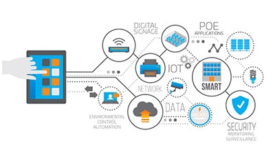
Examples of UTG applications include:
- Building environmental control automation
- Security monitoring and surveillance
- Digital signage systems
- Enhanced PoE applications
- IoT devices and sensors
- Wi-Fi APs
- VoIP devices
Benefits of a UTG infrastructure solution
- Support for IT/OT network convergence
- Advanced power distribution
- UL certified for extended-reach applications
- Optimized bandwidth for devices and applications
- Improved scalability and design flexibility
- Reduced strain on infrastructure
- Extended cabling lifespan is more sustainable
- Improves network reliability and reduces costs
- Centralized management and security
It will take time for the standards bodies to catch up to the extended-reach performance of the UTG infrastructure platform. Therefore, CommScope has worked alongside Anixter, UL and other third-party technology experts to validate all performance claims. These efforts have resulted in UTG-specific performance standards and UTG-rated infrastructure cabling solutions. Together, they support diverse applications, systems and devices on a common network.
All performance claims and UTG ratings are independently tested and verified by UL laboratories for optimal application assurance and design on a single building platform. The results are based on real-world, definitive application testing and UTG-exclusive testing protocols. Based on UL’s testing, CommScope’s UTG solutions outperform non-UTG cabling.
Customers deploying UTG infrastructure solutions enjoy a similar level of application support available through CommScope’s SYSTIMAX Application Assurance program. This support provides the design capabilities and performance helps building owners and enterprises need to migrate with confidence. In fact, the UTG program is highly complementary with the SYSTIMAX Application Assurance program, and we believe we can build on it to extend beyond what we currently support.
CommScope continues to focus on innovation and continual improvement, investing almost $200 million in R&D, including investments in our SYSTIMAX solutions. These investments, combined with a UL verification program to validate emerging and enhanced technologies, give our customers the satisfaction of knowing their CommScope products and solutions are indeed best-in-class.

For more information on CommScope’s UTG infrastructure portfolio:
GigaREACH™ XL
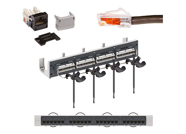
Whereas the UTG infrastructure enables a platform solution for supporting large numbers of connected devices over extended distances, GigaREACH XL supports a small number of devices with the reliable performance of a standards-based connection. Backed by SYSTIMAX Applications Assurance warranty, GigaREACH XL is the first extended reach Category 6 UTP solution that warranties support for:
- 100 Mbps/90 W up to 200 m
- 1 Gbps/90 W up to 150 m
- 10 Mbps/90 W up to 250 m
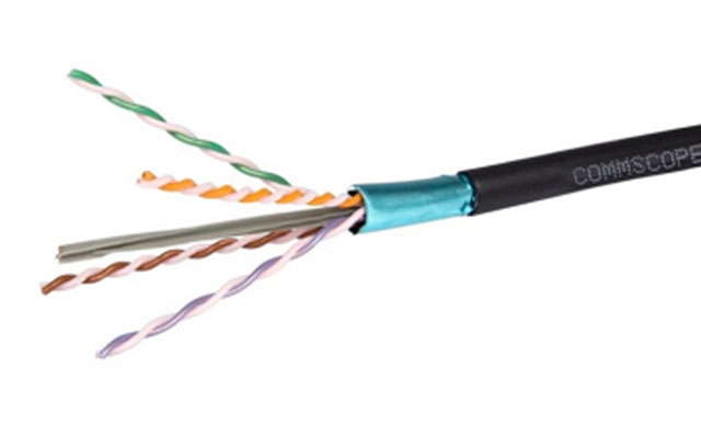
The Cat 6 solution features a proprietary twist technology that enables use of the industry’s lowest loss conductor. The 21 AWG conductor reduces direct current (DC) resistance to 4.69 ohms/100 m—half the DC resistance allowed for standardized Category 6 cables—while lowering insertion loss and voltage drop over distance. This improves energy savings and sustainability and provides a higher power budget over longer distances.
Available as plenum, riser-rated, and outdoor buried solutions, GigaREACH XL is suitable for most environments, and it is compatible with existing structured cabling architectures. It uses the same installation tools, procedures, panels and jacks as SYSTIMAX GigaSPEED® X10D® solutions.
GigaREACH XL benefits
- Warrantied data/PoE performance
- Industry’s lowest loss conductor
- Reduced voltage drop over distance
- Half the DC resistance of standard Cat 6
- Lower energy use, more sustainable
- Supports network convergence
- Works with existing structured cabling
- Application Assurance/25-yr warranty
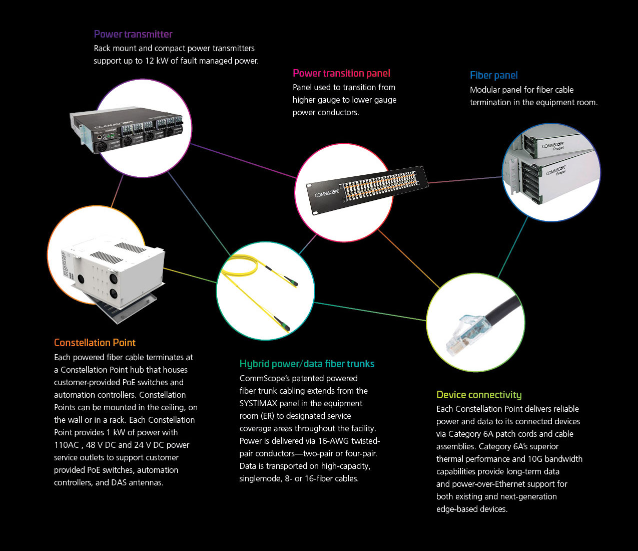
Constellation building edge platform
Constellation™ is a streamlined, modular and adaptable power/data platform that simplifies the cost and complexity of connecting edge-based devices and services. It combines fault managed power, hybrid power/data fiber, and Constellation Point hubs deployed in a distributed star topology. The result is a simplified, scalable and sustainable infrastructure that delivers 10X the power and 5X longer reach than a traditional Category 6A plenum LAN.
The solution supports converged and segmented networks, alternating current (AC) and DC power applications, and a variety of connectivity options with near-unlimited fiber bandwidth at the edge. The Constellation platform is based on modular components deployed in a simplified, repeatable architecture.
The streamlined modular design and simplified distributed star topology provide the following critical benefits:
- Use 50% less equipment, 59% less copper and 65% less plastic than a traditional Category 6A plenum LAN installation.
- Reduce deployment time and costs 57% and skilled labor requirement by 50% or more compared to traditional Cat 6A plenum LAN.
- Support an unlimited number of devices with up to 12 kW of power and nearly limitless data capacity over spans of up to 500 m (1,640 feet).
- Support converged, discrete and hybrid IT/OT networks.
- Eliminate the need for a telecom room on each floor.
Constellation benefits
- Up to 12 kW of fault managed power
- 10X the power, 5X the reach1
- Support any number of devices up to 500 m
- 50% less equipment, 59% less copper1
- Save up to 57% in deployment time/costs1
- Use less energy, extend network lifespan
1Compared to traditional plenum Cat 6A LAN
Powered fiber
Yet another option is to deploy hybrid cables containing copper conductors and fiber-optic cores that feed power and data to PoE extender devices. This powered fiber approach can extend network coverage up to 3 kilometers (15 W), making it a good alternative for in-building and campus-wide applications.
Powered fiber provides a complete power and data delivery platform. It includes DC power distribution and rectification modules, hybrid power/data fiber cabling, PoE extenders and surface-mounted boxes. The low-voltage power is sourced from a centralized primary or backup uninterruptable power supply (UPS). One power supply can drive up to 32 devices simultaneously.
A key difference between powered fiber cable and PoE-enabled Ethernet is that the copper conductor in a powered fiber cable carries no data; therefore, it can be optimized for power. While a Category copper cable uses wires of 23-26 AWG, the powered fiber cables use copper wires of gauges ranging from 20 AWG to 12 AWG, enabling it to increase the current-carrying capacity. Data is transmitted using from one to 12 optical fibers, either G657 A2 singlemode or OM3 and OM4 multimode.
Because the solution uses low-voltage technology, installation and setup are less costly than tapping the power grid, and they require no electrical skilled labor or special conduit. As a result, powered fiber addresses many of the installation and management issues created when trying to extend the cabling network’s reach by adding more telecom rooms or using PoE extenders.
POWERED FIBER BENEFITS
- Low-voltage cable needs no special routing/conduit
- Increased design flexibility and installation safety
- Reliably delivers 15 W of power up to 3 km
- One UPS powers up to 32 devices simultaneously
- 1–12 optical fibers, multimode or singlemode
Powered fiber is widely used in situations where large areas need to be cost-effectively served by a single power and data network. Popular applications include campus environments, airports, parking areas, stadiums, small cell base stations, fiber to the room and more. The solution can also support passive optical network (PON) applications.
This technology continues to evolve in support of longer distances, higher bandwidth, and higher power levels. CommScope anticipates multiport versions of the Powered Fiber Cable System, which currently supports only one connection per cable. We also plan to support the new 802.11ac Wave 2 access points requiring up to 6.9 Gbps connectivity as well as 60 W devices.
Learn more: Powered fiber fact file | CommScope
Cabling parameters that can affect reach and performance
Multiple characteristics, both electrical and physical, impact a cable’s ability to adequately sustain signal performance over the length of the channel. Electrical parameters include insertion loss, resistance unbalance, propagation delay, and mismatched impedance; physical variables include the conductor’s diameter, cordage design and the category of cable used.
Insertion loss (attenuation)—the reduction in the electrical signal strength as it propagates along the transmission path—is present in all media types. It determines the maximum distance over which a transmitted signal can be resolved and, therefore, the maximum distance two devices can be separated while maintaining communication.
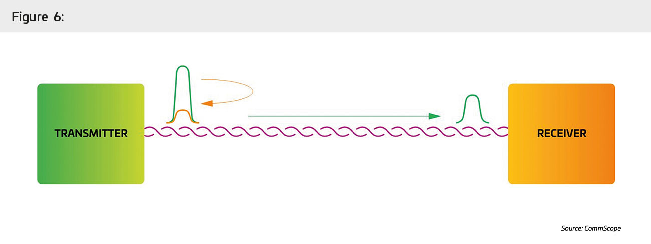
Usually expressed in decibels per unit length (e.g., dB/1,000 feet), insertion loss is a measure of how much the signal’s amplitude is weakened or reduced in amplitude as the signal traverses the cable. It also increases as the cable’s operating temperature increases.
In a copper wire, insertion loss is caused by two main factors:
Copper loss is related to the thickness of the cable’s copper conductor; the thicker the conductor, the lower the insertion loss. While you can reduce insertion loss by increasing the conductor size, that would increase cabling costs and reduce your options for properly mating the conductor to the right jacks and/or plugs. In reality, an oversized conductor is unnecessary for the vast majority of installations that are less than 100 m in length.
Dielectric loss (dissipation) is related to the electrically lossy properties of the cable’s insulation and jacketing. The choice of these materials impacts insertion loss and the cable’s performance during safety tests such as those that characterize flammability and smoke release. Tradeoffs between electrical and safety performance often dictate the materials needed, which can complicate compliance with regional safety standards such as those for plenum-rated and low-smoke-zero-halogen (LSZH) rated environments.
It’s important to note that there are other factors, such as resistance and heat, that can influence insertion loss. For example, the maximum allowed insertion loss for Category 6A (at 500 MHz) is 42.8 dB, compared to Category 6 (at 250 MHz), which is 31.1 dB. This is also why links involving smaller-gauge wires with more resistance—and where the ambient temperature is above 20°C (68°F)—can require length de-rating. The higher the insertion loss, the shorter the reach must be for a signal at the far end of the link to be understandable. This is a key reason why insertion loss has such an important impact on the supported distance.

SNR is directly related to insertion loss. Measured in decibels, it expresses the ratio of a link’s signal power compared to the noise power for a given frequency range. The higher the ratio, the better the signal quality. SNR and insertion loss are inversely related—the lower the insertion loss, the higher the SNR. Just as insertion loss increases with distance, so too SNR is affected by cabling length. Should the SNR drop to unacceptable levels, either the transmission or cable length must be reduced to support the application.
Conductor size will also affect maximum cable length. The amount of resistance is inversely proportional to the thickness of the gauge (due to the skin effect). Therefore, larger gauge wires will exhibit better insertion loss.

Electrical resistance is the conductor’s ability to resist the flow of electrons. DC loop resistance, measuring the resistance of two connected DC conductors, indicates how efficiently the loop delivers power in a PoE application. ANSI/TIA-568.2-D and TIA TSB-184A D3.0 specify that DC loop resistance (resistance unbalance) for Category 3/5e/6/6A shall not exceed 25 ohms; exceeding the DC loop resistance limit creates heat within the cables, which increases insertion loss and reduces the acceptable link span. To ensure safe operation over extended distances, many extended-reach cables include additional resistance headroom to account for the unbalance.
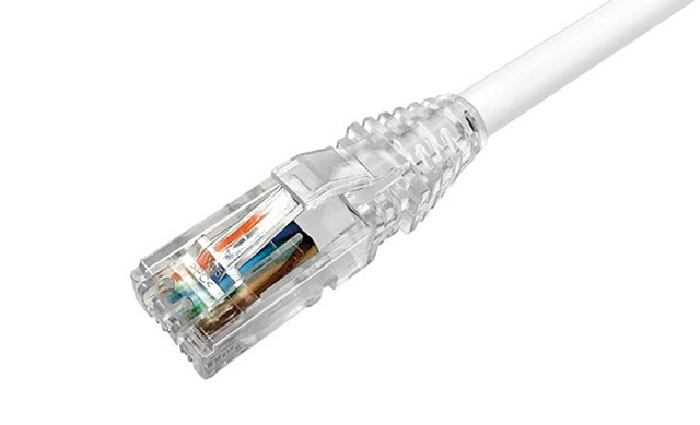
The first Cat 6A cables and patch cords were bulky and rigid. Newer patch cords employing smaller conductors (usually stranded and thinner than 24 AWG) are appreciated by customers given their flexibility and the lower volume they fill in cord organizers. However, smaller conductor cords, no matter how short they are, have an impact on the total insertion loss and may also imply some length de-rating. There is a balance to be found between comfort and performance!
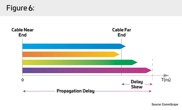
Propagation delay is the time needed for a signal initiated at one end of the channel to be received at the opposite end. In twisted-pair cabling, this time interval is impacted by the cable’s length and operating frequency (previously discussed) as well as a third factor: nominal velocity of propagation (NVP). NVP is a relative measure of the signal’s speed compared to the speed of light in a vacuum (c). Typical structured wiring cables exhibit an NVP of 0.6 c to 0.9 c, meaning the signal travels at 60–90% the speed of light in a vacuum.
A cable’s maximum NVP is dictated, in part, by physical characteristics such as the number and tightness of twists in a pair of strands. As the number of twisted pairs in a cable bundle increases, the chances of disparities in the twists among pairs also increase. The difference in propagation speeds between the fastest and slowest pairs is known as the “propagation delay skew.” As propagation delay skew grows, the more difficulty the network equipment has in reading the signal. Extended cable lengths can exacerbate this issue.
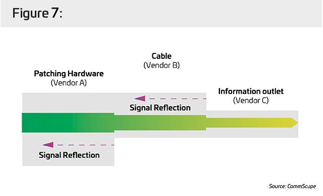
channel composed of cable and connectors with different or mismatched impedance will exhibit poor return loss, caused by all the reflections originated at the connection.
In the SYSTIMAX GigaSPEED X10D solution, all the termination hardware, equipment and work-area cords are designed to match the impedance of the cable, providing a “tuned” channel that ensures optimum performance.
When we compare the different categories’ performances in light of the aforementioned parameters, it’s easy to understand the advantage of Cat 6A when we need to go farther than the standard 100 m:
- At 100 MHz, Category 5e has an insertion loss maximum of 24 dB, while Category 6 is at 21.3 and Category 6A is at 20.9 (per TIA channel specifications). Remember: The lower the dB for insertion loss, the better.
- Common 6A cable and cordage gauge is larger (thicker) than for other categories, which improves insertion loss, resistance and SNR parameters.
- Cable heating is lower for 6A when transmitting the same current and wattage for PoE purposes, which makes possible larger cable bundles.
- As previously mentioned, first-class 6A solutions are carefully tuned up to provide lower signal reflection.
- All of the above advantages, combined with the inherently superior performance for alien crosstalk, make Cat 6A the perfect choice.
Conclusion
The changes in how organizations deploy, use and manage data are, in a word, transformative. Increasing use of augmented reality, IoT, and building automation/control are leading to increased workforce productivity, collaborations, and safety, and buildings that are more efficient and sustainable. For network managers, however, designing networks that can support and sustain these new capabilities is a significant challenge.
While networks—including IT, OT, power and data—are converging to become more efficient, the number of connected devices and systems is exploding and moving to the network edge, closer to where data is being created and consumed. Supporting these changes means rethinking the role, design and capabilities of the structured cabling infrastructure, something CommScope anticipated years ago.
As an industry leader and innovator, we began working long ago with UL, Anixter and other network engineering specialists to develop an evolutionary unified infrastructure platform: UTG infrastructure. Meanwhile, our on-going work in cable re-engineering and sustainable network architecture has produced GigaREACH XL5, the powered fiber cabling system and the Constellation building edge platform. Now, customers can confidently extend the reach of their structured cabling networks to support tomorrow’s next-generation connected devices and systems.
For more information on CommScope’s portfolio of Extended Reach solutions for the enterprise, visit www.systimax.com


Getting Past the 100-meter Gorilla Holding Your Network Hostage
Innovative strategies to extend your network’s reach in a disruptive environment